

How To Draw Model Airplane Plans
In this tutorial I will show yous how I build an Arduino based RC Airplane, and also, I volition testify you how to control it using the custom build Arduino transmitter that I built in i of my previous videos.
You can lookout man the following video or read the written tutorial below.
Overview
And then, the airplane is entirely made out of Styrofoam. For making the shapes I used my Arduino CNC Cream Cutting Machine which I already showed you how I congenital it in a previous video. Although I'm using a CNC machine for building this Arduino RC airplane, I can still say information technology's 100% DIY because the CNC machine is likewise a DIY build.
Moreover, the control of the airplane is also 100% DIY, based on Arduino and the NRF24L01 module for the radio advice.
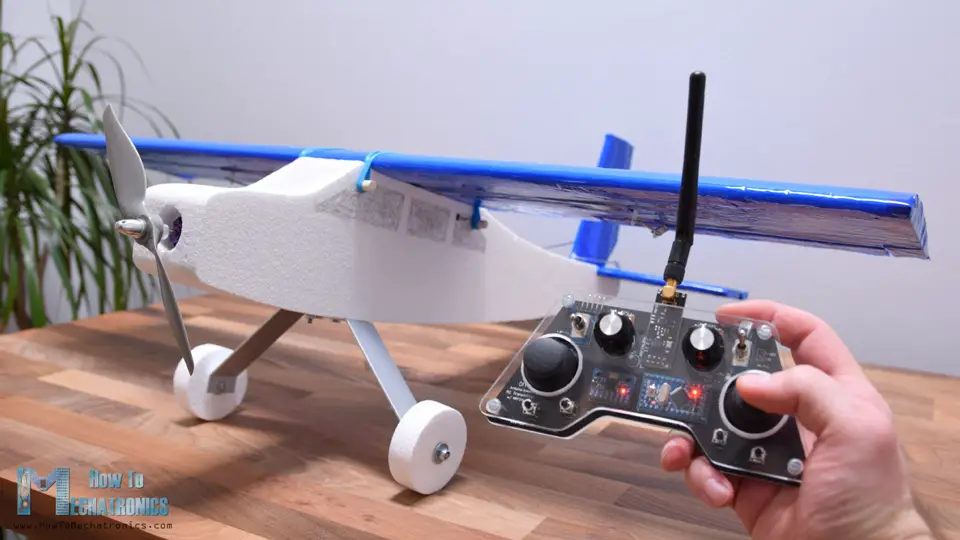
Using the right joystick of the transmitter, we can command the ailerons and the elevator of the airplane, and using the left joystick we can command the rudder and the throttle.
In addition to that, using the correct potentiometer we can adjust the controls responsiveness, or reduce the corporeality of servo travel, and using the left joystick we tin can sub-trim the rudder or adjust the neutral position of the servo arm.
Oh, and I virtually forgot the mention, the main characteristic of this Arduino RC plane is flying, so yeah, it can wing.
Designing the RC Airplane – 3D Model
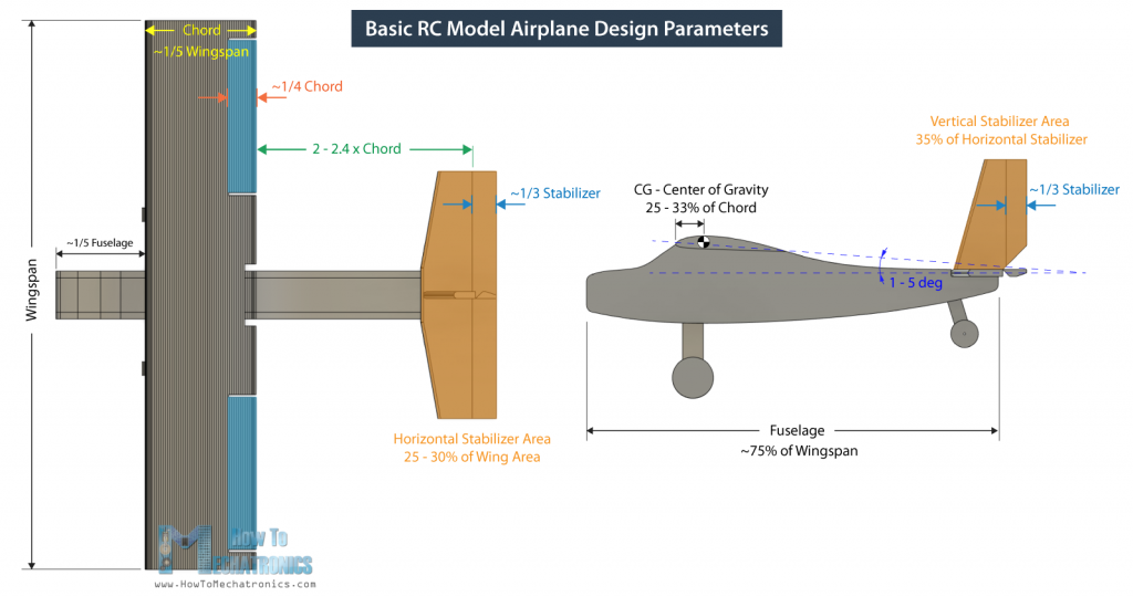
I started past designing the plane using a 3D modeling software, Fusion 360 in this case. I fabricated the design by looking at some commercial RC airplanes and following some basic guidelines or rule of thumbs for model aeroplane parameters.
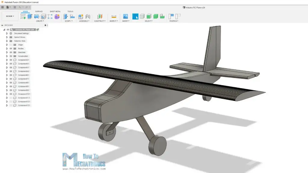
The starting point is the wingspan, and I chose to be 80cm. From there we become the fuselage length, which is by and large 75% of the wingspan. As for the airfoil, or the wing cross section I chose the CLARK Y Airfoil, which a pop choice for RC airplanes.
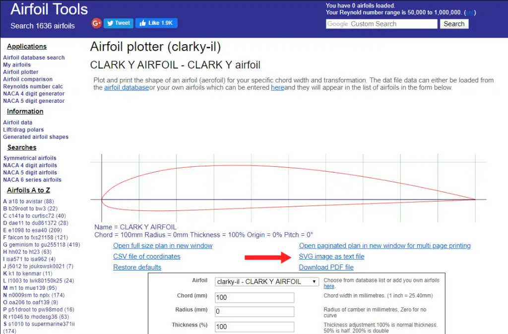
I downloaded the airfoil shape from airfoiltools.com as .SVG file and then I imported it into Fusion 360. I adjusted the size appropriately, and then that the wing chord, or the length of the fly in stream-wise direction is around 1/fifth of the wingspan.
The horizontal and the vertical stabilizer are also sized according to those basic guidelines. Hither are some those basic RC model airplane design parameters:
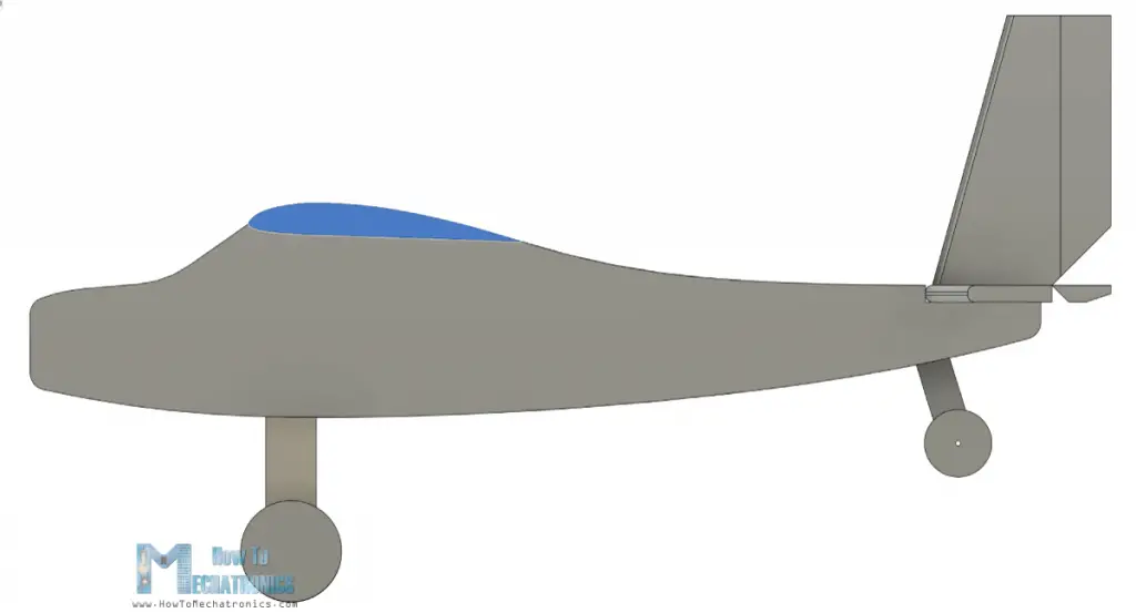
The fuselage of the airplane will be made out of two 10mm sides and a 50mm core which will exist hollow to accommodate the electronics.
Y'all can download the 3D model from the links higher up. There are ii version of the Airplane. The version 1 is the one shown hither in the images, and version two has a chip smaller nose and the motor can be placed more to the front in order to ameliorate airflow.
Generating Yard-codes for my DIY CNC Foam Cutter
Now, as my Arduino CNC Cream Cutting Auto piece of work area is limited to 45cm, and the fuselage is 60cm in length, I had to brand the fuselage out ii parts.
So, I cut the fuselage at 34cm from the front point, and made a new sketch in which I projected the shape and added a bespeak near it. Next, in the manufacturing tab of Fusion 360, I can generate the G-code for cutting the shapes.
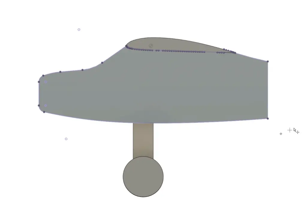
Here, beginning I fabricated a new setup where I selected the sketch as a model, selected the bespeak I added before as origin for the setup, and adjusted the X and Y centrality appropriately.
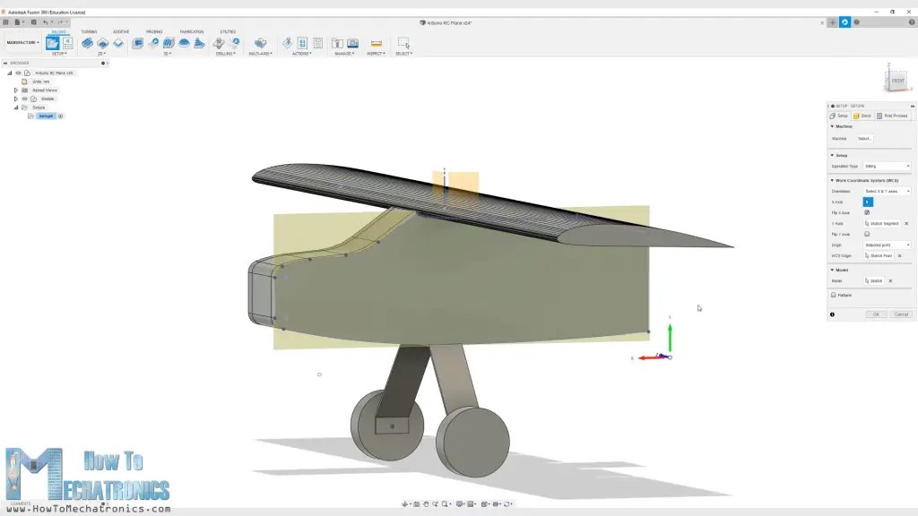
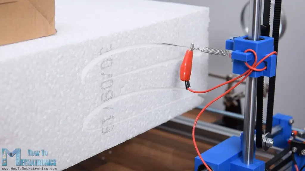
So I chose the 2D profile operation and selected or generated a new tool, with bore of 3mm, because that'southward the approximate size of the cuts that the hot wire makes when passing through the Styrofoam. Here nosotros can also set the cutting feedrate which depends on the hot wire itself and the hardness of the Styrofoam. I gear up it to 150 mm/1000.
Then in the geometry tap we can select the contour or the shape that needs to be cut. As for the heights I gear up them all to 1mm as there isn't any Z axis movement on my foam cutter auto. Lastly in the Linking tap I selected the entry position to exist the border located almost the origin point.
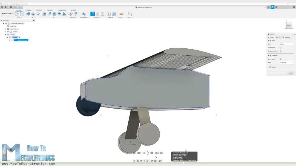
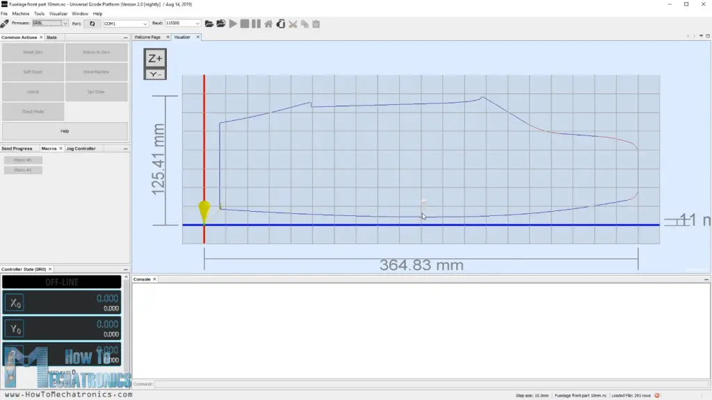
With this the toolpath is generated and we can take a await at information technology by clicking the Simulation button. The toolpath should be a airtight loop single laissez passer, and if that's the case, we tin finally generate the Grand-code. For that we can become to Post Processes, select the GRBL firmware, select the output folder, name the file and click the postal service button.

Then nosotros can save the file, and we can run across the Thousand-code in the WordPad editor or something similar.
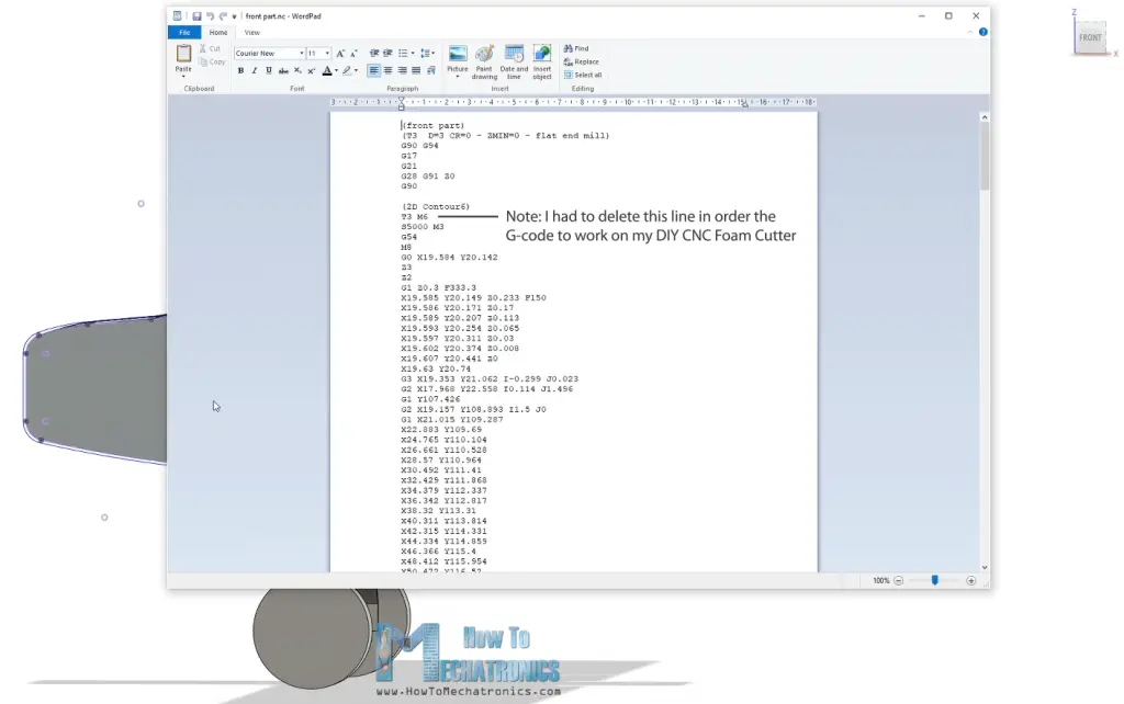
Then now once we have the Chiliad-code file, nosotros tin load it into the Universal G-lawmaking sender and send the G-code to the CNC auto to brand the shape.
Nosotros tin note that the process that I've only showed you is probably not the best one or not professional at all, but still it does the job for getting the Yard-codes to work with my DIY CNC Foam Cutting Automobile. Of course, for more details nearly this DIY CNC automobile you tin check my item tutorial for it, the link is in the description of the video.
You tin download the G-code files here:
Every bit I said, for the sides I used 1cm tick Styrofoam and for the middle I used 5cm tick Styrofoam.
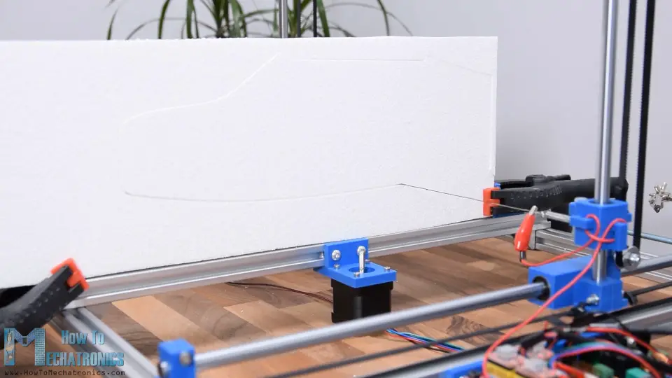
As for the wing, I used 10cm tick Styrofoam which I cut it around 30cm wide because that's the maximum bridge my hot wire auto tin cut. I placed ii wing profiles in single Thou-code file and I cutting couple of them.
In club to get the 80cm wingspan I volition glue 3 pieces of 27cm, and in order to get them straight, I manually cut off the ends of the pieces and so that they are perpendicular.
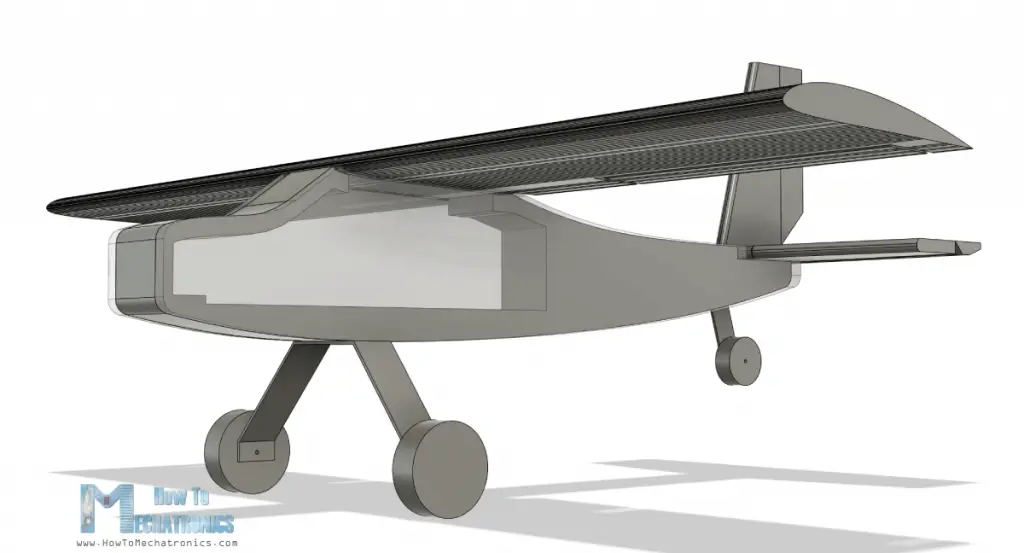
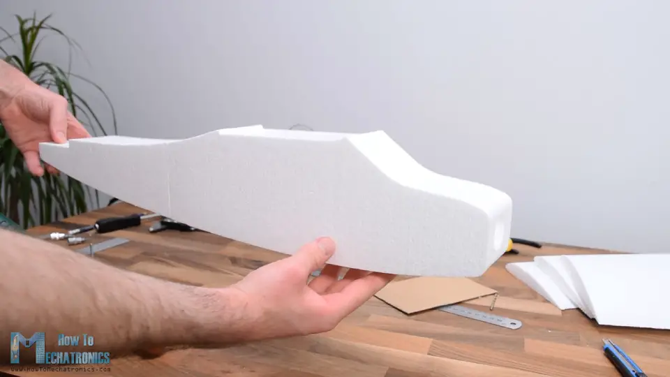
Assembling the RC Airplane
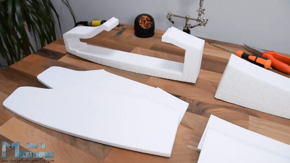
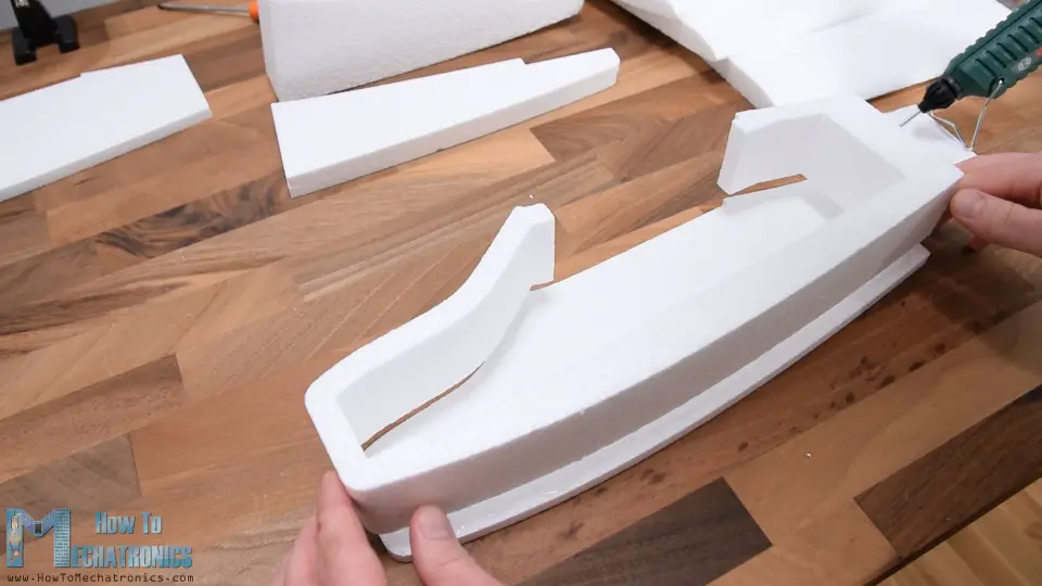
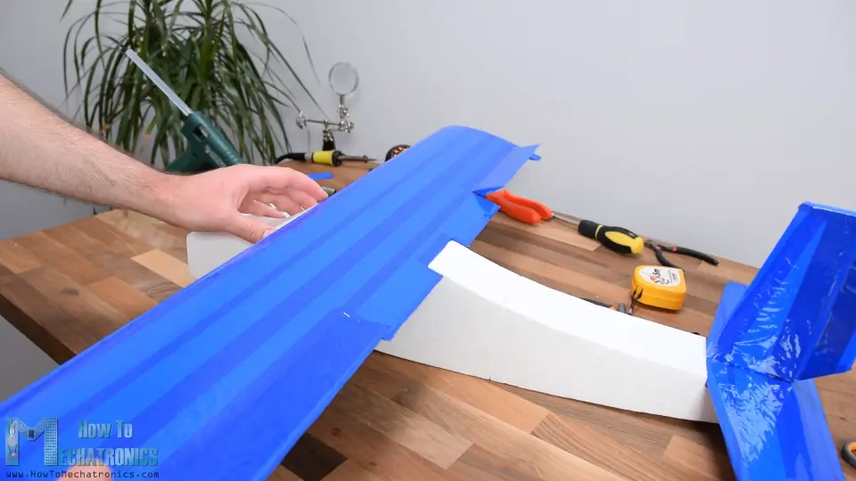
And then here are all the Styrofoam pieces I cut with CNC automobile. Three pieces for the front, three pieces for the back and three pieces for the wing. Now I can first assembling them.
I will start with the front part. I'm using a glue gun for gluing the pieces together. The hot glue was melting a little bit the Styrofoam but even so I was able to mucilage them using this method.
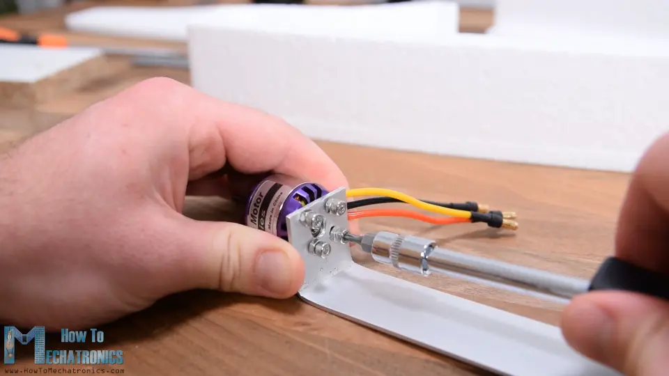
Another proficient way to gum Styrofoam is with 5-minutes epoxy. Before gluing the other side, I volition make the holder for the motor. For that purpose, I'm using 30mm wide aluminum profile which is pretty low-cal weight. I cut the contour at around 18cm, marked the holes for mounting the motor, and drilled them using 3mm drill chip. Then I aptitude the profile at 90 degrees. I secured the motor to the holder using some M3 bolts.
Using this assembly, I made a pigsty through the forepart part of the Styrofoam. Then, using a utility knife, I enlarged to hole to 30mm in diameter, same every bit the motor diameter.
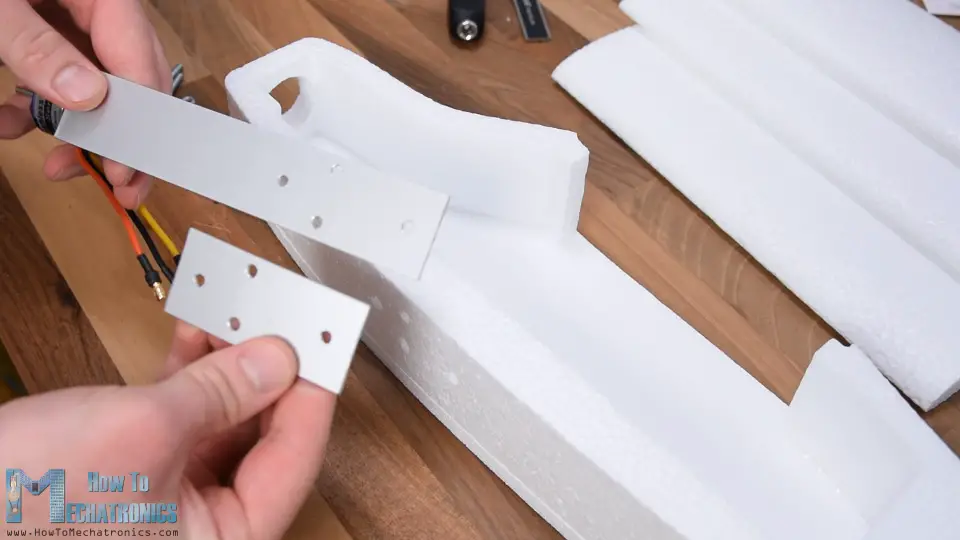
Next, on the other side of the motor holder I made 4 holes which volition serve for securing the holder in place and also for attaching the landing gear. I marked the location of these holes on the fuselage and using a 4mm drill bit I made holes through the Styrofoam manually. I fabricated another aluminum piece around 7cm long with the same holes, and now I can utilise information technology for securing the motor holder.
Using M4 bolts we can hands secure the motor holder in place without dissentious the Styrofoam. However, I will do that after, and so I removed them and I continued with gluing the other side. Using the same method, I glued the back pieces as well.
The adjacent stride is the union, or connecting the front and the back part of the fuselage. In order to make the connection stronger, I will add simple barbecue sticks in between them.
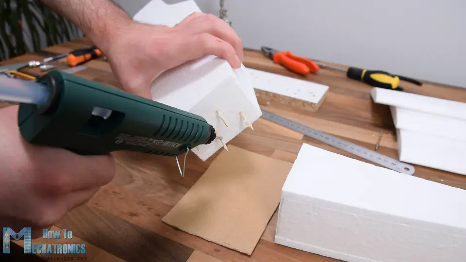
I would suggest even using some bigger sticks because when the airplane will crash it might hands break here. I added some decent amount of hot gum to the connecting site and squeezed them together. So here information technology is, the fuselage is ready and I remember information technology looks pretty cool.
Next, using a utility pocketknife I'm cutting two pieces of x mm stick Styrofoam which will be the horizontal and the vertical stabilizers. I askew the edges so they await meliorate and also be a little more aerodynamic. The stabilizers volition exist directly glued to the back side of the fuselage but before I practice that, I will first brand their controller surfaces.
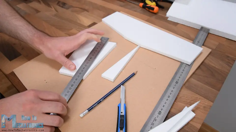
For that purpose, I cut around 1/tertiary of their length, and that will be their control surface or the elevator for the horizontal stabilizer and the rudder for the vertical stabilizer. In order to be able to hinge the command surfaces on the stabilizers I needed to bevel their contact surface. Over again, I did that using a utility pocketknife, and we actually need quite sharp one for getting these cuts clean.
I connected with making the stabilizers a bit more than aerodynamic. For that purpose, I used a sandpaper and made their leading edges rounded. I also sanded the trailing edges a little bit.
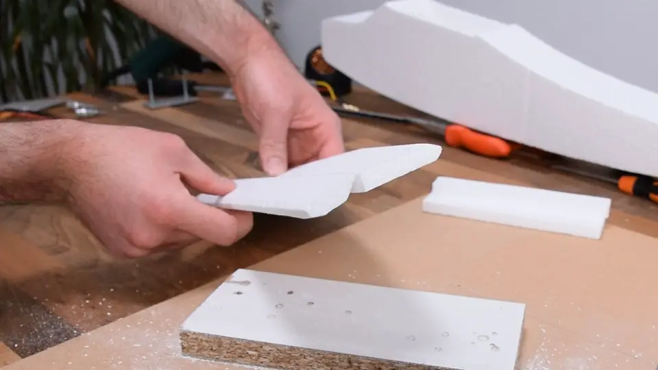
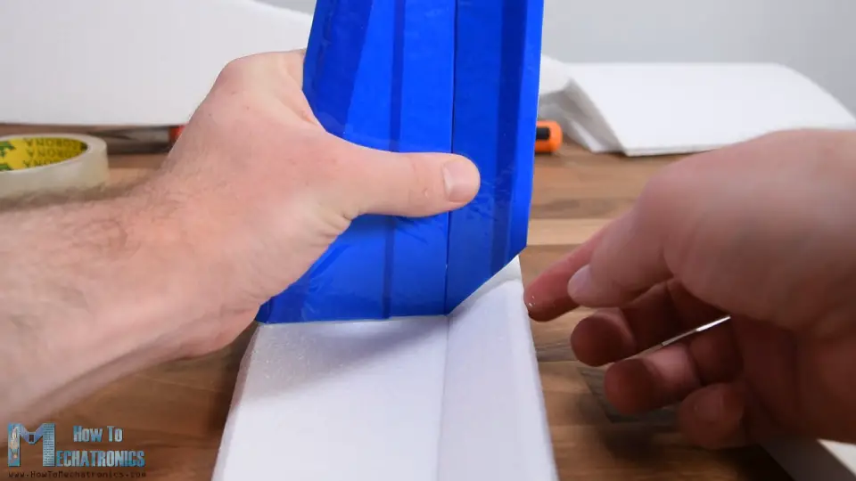
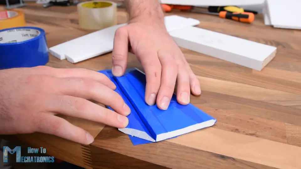
At present, as the Styrofoam is quite fragile, I'm going to wrap the whole area of the stabilizers and their control surfaces with a uncomplicated packing record. This will not but make the parts stronger just also increment the aerodynamic, every bit the record is much smoother than the Styrofoam itself.
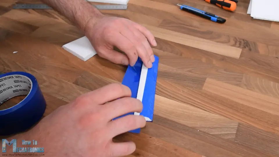
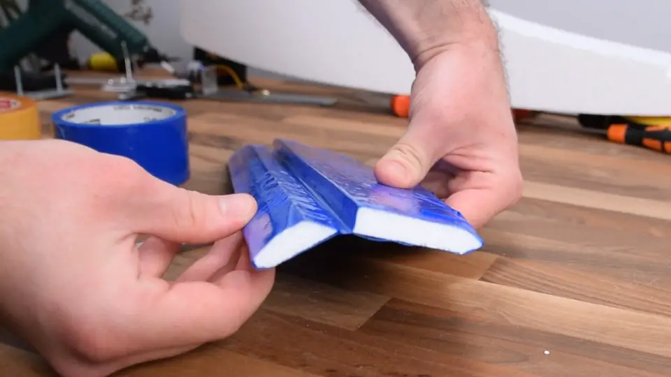
After wrapping it, I cut the rudder bottom part at 45 degrees, in order to brand space for the lift to be able to move freely.
Now finally, I can make the hinge for it, and I'g doing that using the packing tape again. So, I simply connected the two parts together with the record, and that makes quite strong hinge.
I repeated this process for the horizontal stabilizer as well. For making the hinge fifty-fifty stronger we tin can likewise add together tape on the other side. Using the same record, I wrapped the sides and with that the 2 stabilizers are washed.
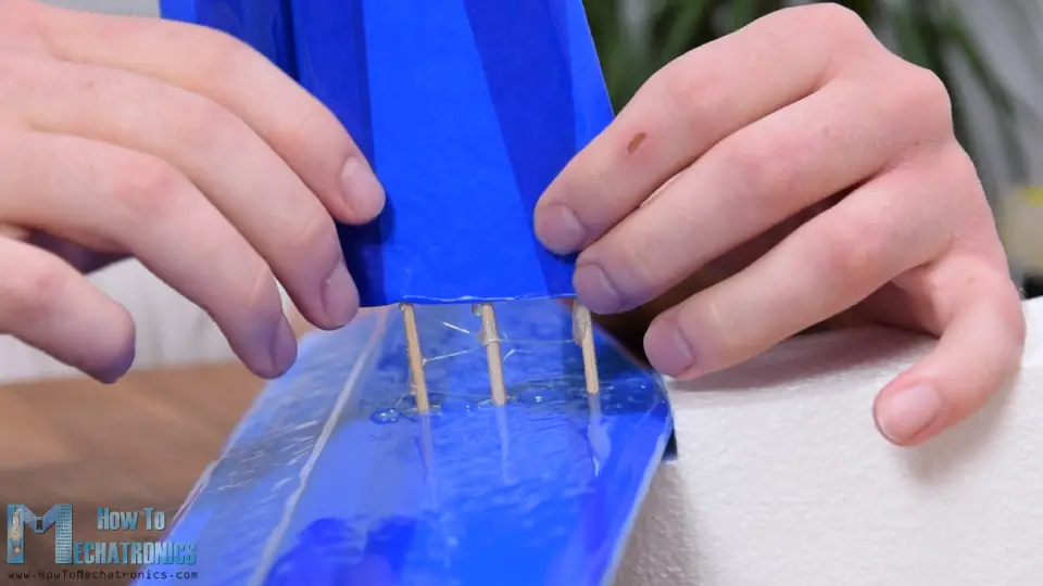
I moved on with gluing the horizontal stabilizer to the fuselage using a hot glue. For securing the vertical stabilizer, first I inserted and glued 3 barbecue sticks through the horizontal stabilizer and the fuselage. Then I put some hot gum on them and the contact surface and pushed the stabilizer down firmly.
With this we are done with the stabilizers and we tin move on with making the fly.
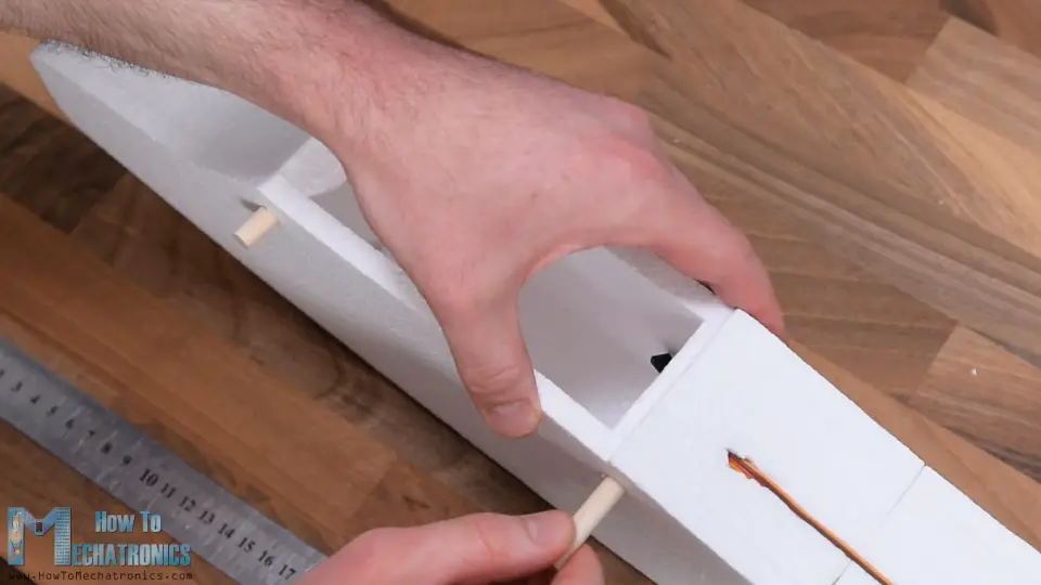
Then, every bit I already said, the wing volition exist fabricated out of 3 pieces because of the limited work area of my DIY CNC foam cut machine. Over again, I'grand using barbecue sticks for providing boosted strengths when gluing the pieces. For attaching them precisely in line, I'm using a direct wooden strip on which I can slide the pieces.
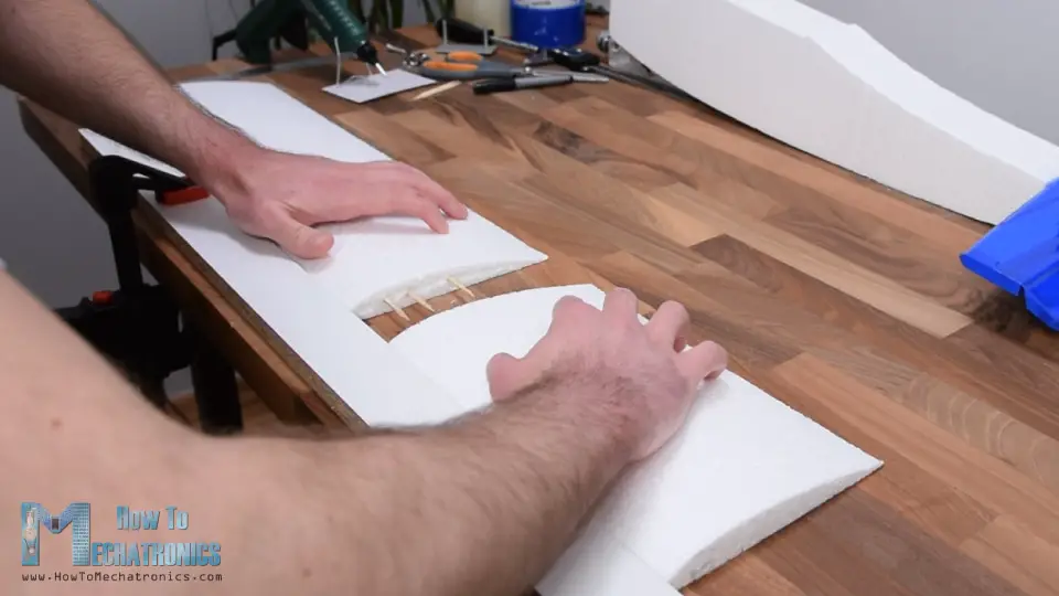
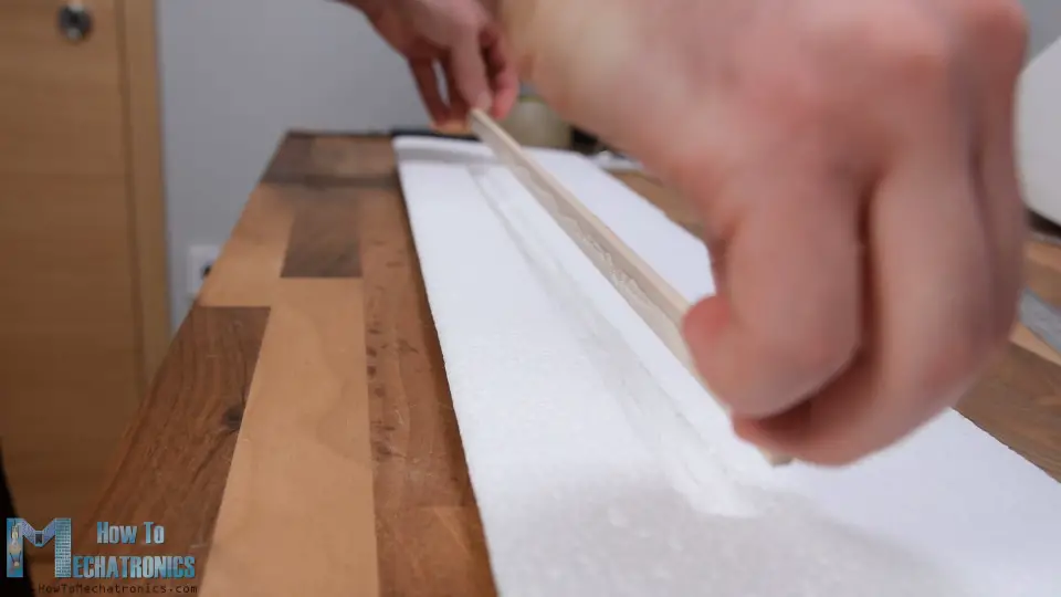
Once done with that, the wing is actually quite fragile as it'southward long and tin can. Therefore, I will reinforce it by adding a wooden stick to it. I cut the stick to size and marked the wing where I need to make a pocket then I can fit the stick in it. Using the utility knife, I slowly and carefully made the pocket. I added some hot glue to it and secured it in place without disturbing the airfoil shape too much.
Now the wing is much stronger with the wooden stick in place. Although stronger it would notwithstanding easily break apart if it hits the ground, so therefore I will wrap information technology all with the packing tape as same as I did with the stabilizers. I started adding the tape from the back side or the trailing edge of the fly, to the front side or the leading border.
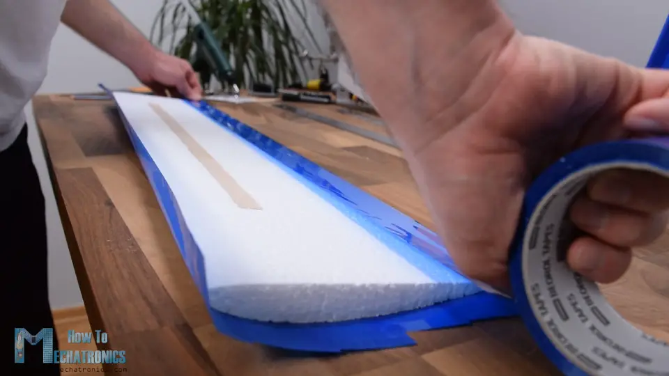
In this way the incoming air from the front won't tend to detach the tape. Although this process looks pretty like shooting fish in a barrel, it tin can exist a bit annoying if yous don't have steady hands and enough patient. I think the wing came out simply perfect. At present it is much stronger, more aerodynamic and it looks quite good.
All right, the next step is making the control surfaces of the wings or the ailerons. I'm going to make them 22cm broad and virtually i/4th of the wing chord in length. In order to be able to move freely I cut off like one-half centimeter of information technology.
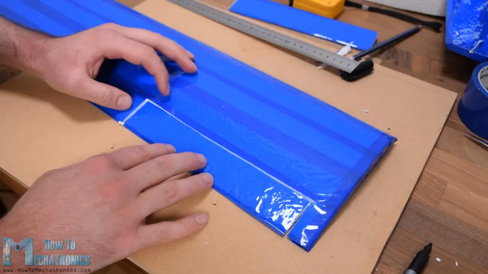
And of course, I wrapped all edges exposed with the cutting. Adjacent, I beveled the bottom part of the aileron at 45 degrees, and in the same manner as show before, at present I tin hinge it to the wing. In order to fit on the fuselage and be able to easily attach the wing to the fuselage I had to make one more than recess in the middle the wing.
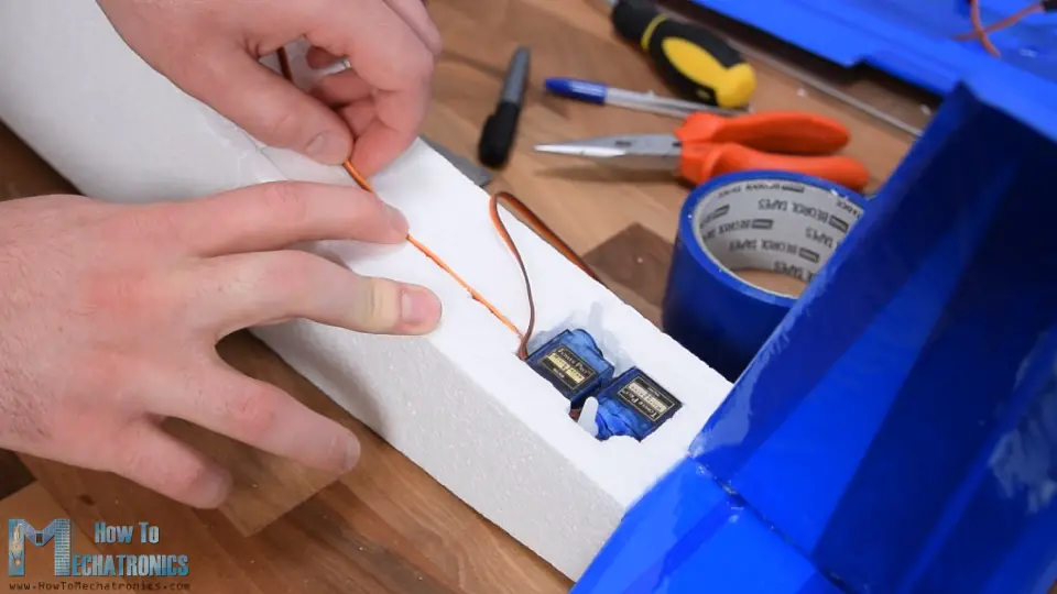
Side by side, it is time to install the servo motors for controlling the ailerons. I'thousand using the 9g micro servos. I marked the location where they will exist placed and using the utility knife, I advisedly made an opening in the fly so that the servo can fit it. Meanwhile, I removed the servos mounting brackets and then that thier shape is simpler. I put some glue on the servo and inserted in the opening.
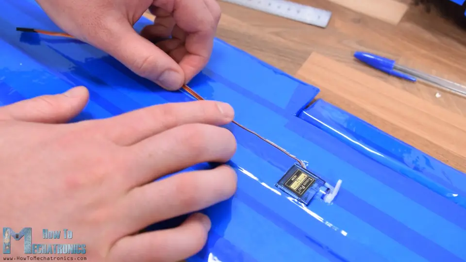
Using the utility pocketknife, I made a pocket-size groove from the servo to the eye of the wing and then that I can fit the servos wiring in it. Finally, I covered everything with a piece of tape. I repeated the same process for the other side as well.
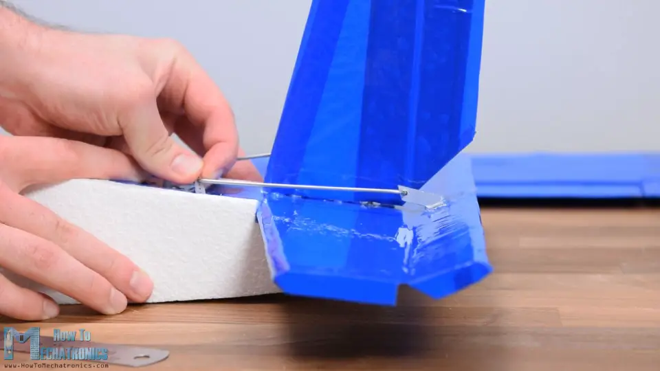
I continued with making the control horns. I'thou going to make them out of the aluminum profile that I used before for making the motor holder. I depict the shape by hand to approximately lucifer the servo motor horn height and to hang over the hinge betoken. I cut the shape using a hacksaw.
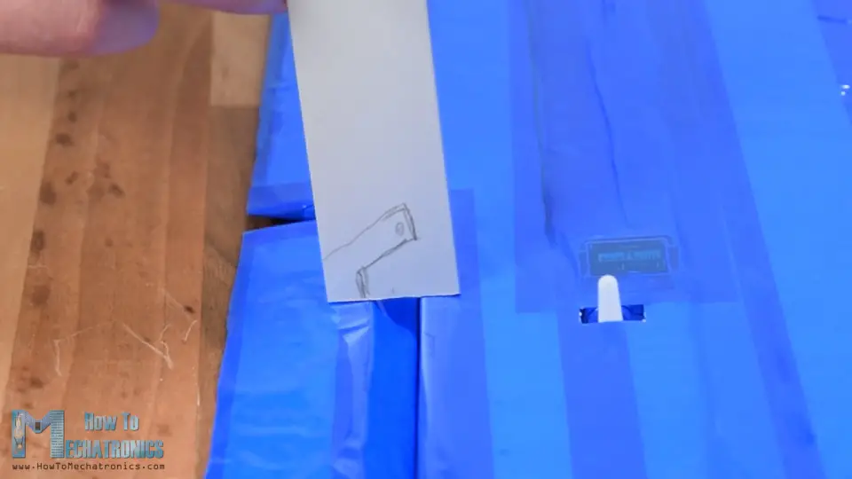
I will use 2mm steel wire as control rod so I fabricated an opening in the horn using a two.5mm drill. I fabricated a small groove in the aileron and glued the horn in place. Then I measured how long the command rod should be and made it out of 2mm steel wire with the help of some pliers. We need to note that when measuring and inserting the control rods, the servo motors need to be in neutral position.
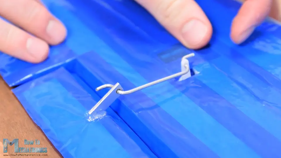
We tin do that by manually placing information technology in the center of its motion range, or past connecting it to a servo tester or do that with an Arduino. I repeated the process for the other side, and with that the wing is now completely washed.
Next, I demand to install the servos for controlling the rudder and the elevator. I'm using the aforementioned 9g micro servos here every bit well, and the process of installing them is really pretty much the same as I've just explained. Showtime, I marked the location, made the opening using a utility knife and glue the two motors in identify. Hither, they are next to each other but with their output shafts on the opposite side.
Once more, I made a minor groove in the fuselage in order to conduct the servos wiring to the electronics compartment. I covered the servos with a slice of record and fabricated openings for the servo horns. In the aforementioned manner shown earlier I made the control horns and glued them in place using a glue gun. Lastly, I made the advisable control rod and installed them appropriately.
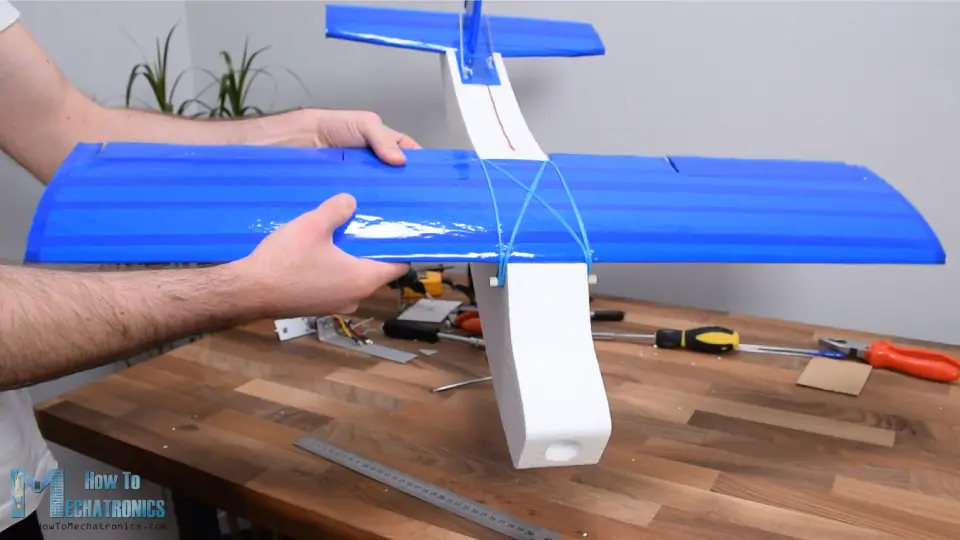
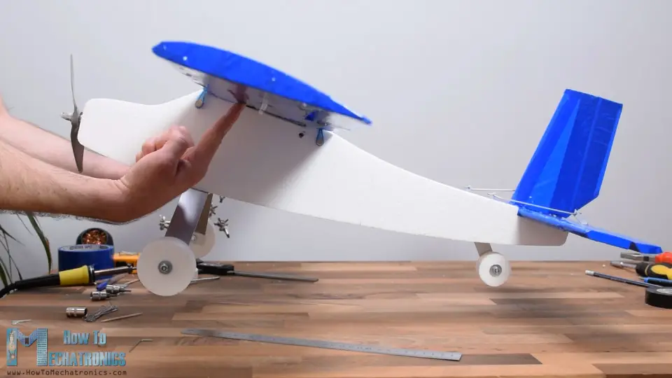
Ok, next I'one thousand going to install ii 8mm wooden rods which will serve for securing the wing to the fuselage. I fabricated the holes manually using a 6mm drill bit. The rods should hang over around 1cm on both sides. I secured them to the fuselage with some hot glue too and here's how they really work.
We use rubber bands for securing the fly to the fuselage. In that way the fly tin can be easily removed and in example of burdensome the rubber bands will significantly reduce bear upon to the wing. At the aforementioned fourth dimension the associates is plenty strong.
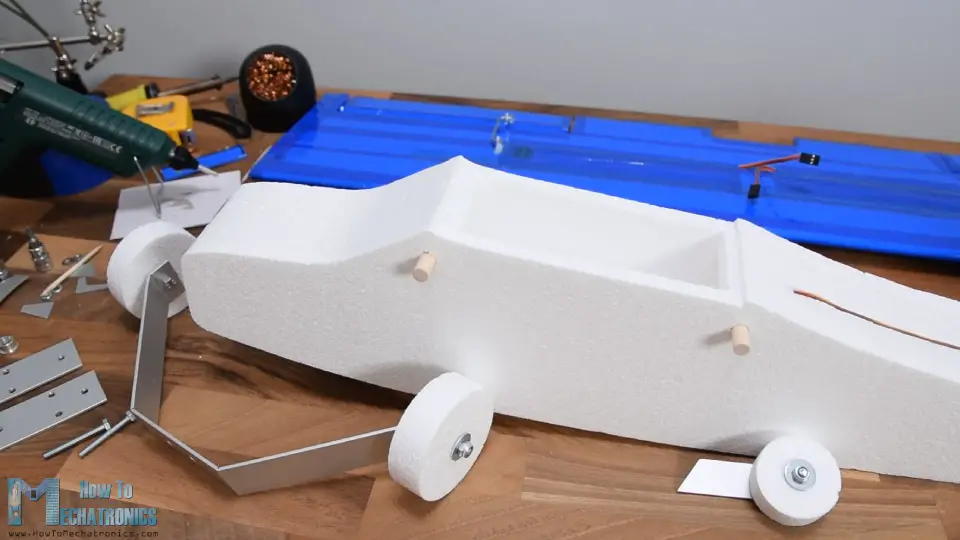
Next, I'grand going to brand the landing gear. For that purpose, again, I'm will apply the aluminum profile and wheels made out of Styrofoam. I made them using the CNC car equally shown earlier. I fabricated petty grooves on the aluminum profile so I tin can easily bend it. Here's how the landing gear should actually look similar.
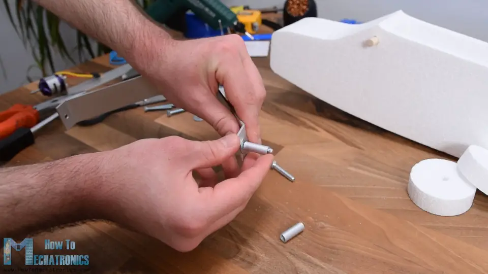
For attaching the wheels to the contour, I will use M5 bolts and an aluminum tube with 6mm inner diameter. The tube is secured to the bracket using the M5 bolt and nut, and on the sides, I added M5 washers so the cycle can rotate effectually the tube freely. With the same method I made the wheel for the back side of the airplane.
Ok, and so now all the components are ready and earlier I assemble them let's take a wait at the electronics of this projection.
Arduino RC Airplane Electronics – Circuit Diagram
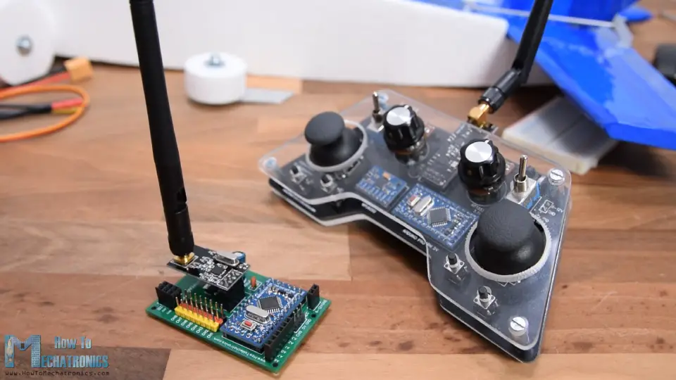
So, every bit I already said, this RC airplane is entirely based on the Arduino, both the Transmitter and the Receiver are custom builds based on the Arduino Pro Mini board.
I already have detailed tutorials how to build and how the transmitter and the receiver work, then you can cheque them out for more than details. Here I volition explain the excursion diagram and the working principle of this Arduino RC airplane and how everything needs to be connected.
You can get the components needed for this projection from the links below:
- NRF24L01 + PA + LNA …………..…..……. Amazon / Banggood / AliExpress
- Arduino Pro Mini………………..……….….. Amazon / Banggood / AliExpress
- Servo Motor …………………………………… Amazon / Banggood / AliExpress
- Brushless Motor ………………………..…… Amazon / Banggood / AliExpress
- ESC 30A ……………………………….………… Amazon / Banggood / AliExpress
- Li-Po bombardment ……………………..…………… Amazon / Banggood / AliExpress
Disclosure: These are affiliate links. Equally an Amazon Associate I earn from qualifying purchases.
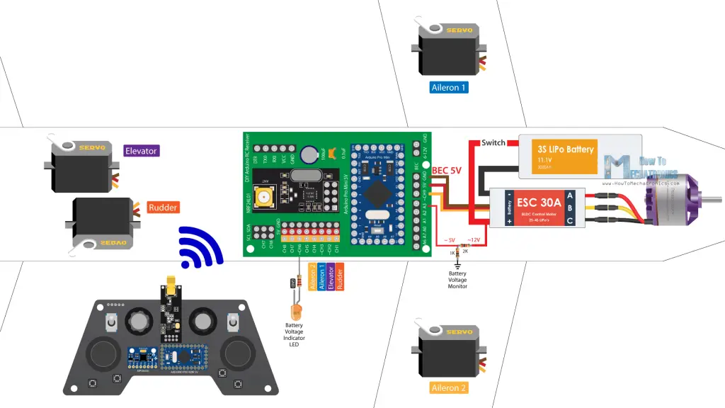
Then, the radio advice is based on the NRF24L01 modules. Although information technology might await a flake complicated, this DIY Arduino transmitter is actually pretty simple. It has several controllers, the joysticks, the potentiometers and some buttons, and it constantly sends their information to the receiver. The receiver accepts this data wirelessly through the NRF24L01 module and it outputs appropriate commands to the servos and the brushless motor for decision-making the airplane.
Controlling servos and brushless motors with Arduino is as well quite simple, and then therefore this unabridged Arduino RC aeroplane concept I remember is not that hard to exist understood. The brushless motor I'g using in this projection has a rating of 1000KV and information technology requires 30A ESC. The ESC drives the motor and also provides power to the Arduino and the servos through its Battery Eliminator Circuit feature which outputs 5V. And the power to the ESC and the brushless motor comes from a 3S Li-Po battery.
I added one more feature to this plane, and that's a elementary LED which volition betoken if the battery is empty. Using a simple voltage divider, we drop the 12V coming from the Li-Po battery to around 5V so we can read them with the Arduino analog input and then know when the battery will drop below 11V. The receiver yet has several gratis channels, so nosotros can add more than features to this airplane if we want, like strobe lights, flaps, dropping mechanisms then on.
Finishing the Assembling
Notwithstanding, let's end the assembly now. So, I connected everything every bit explained in the excursion diagram. On channel 1 is the rudder, channel 2 the elevator, channel three and 4 the ailerons, and on aqueduct 6 the LED. I glued the LED on 1 side and the power switch on the other side.
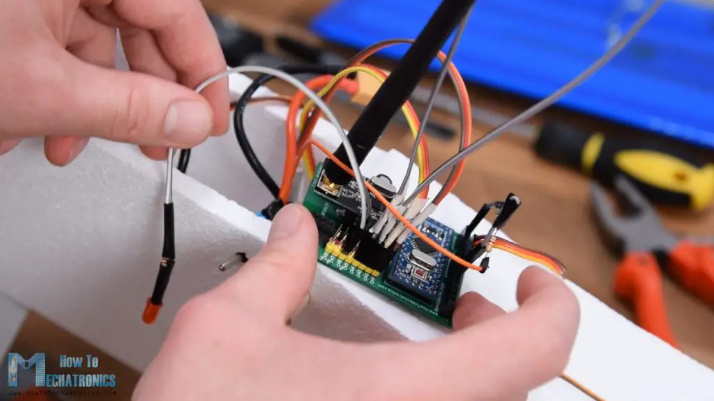
We can annotation hither how the landing gear is attached to the airplane using the two bolts on the motor holder. In few words, I simple inserted the motor with the holder from this summit opening, bolted in identify as prove earlier, and attached the landing gear also. When inserting the holder, I also added some safe bands so they can hold the battery in place.
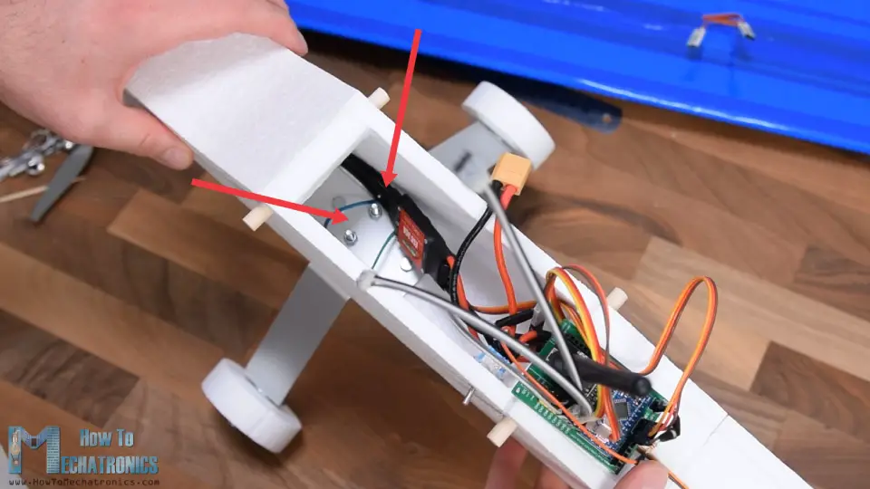
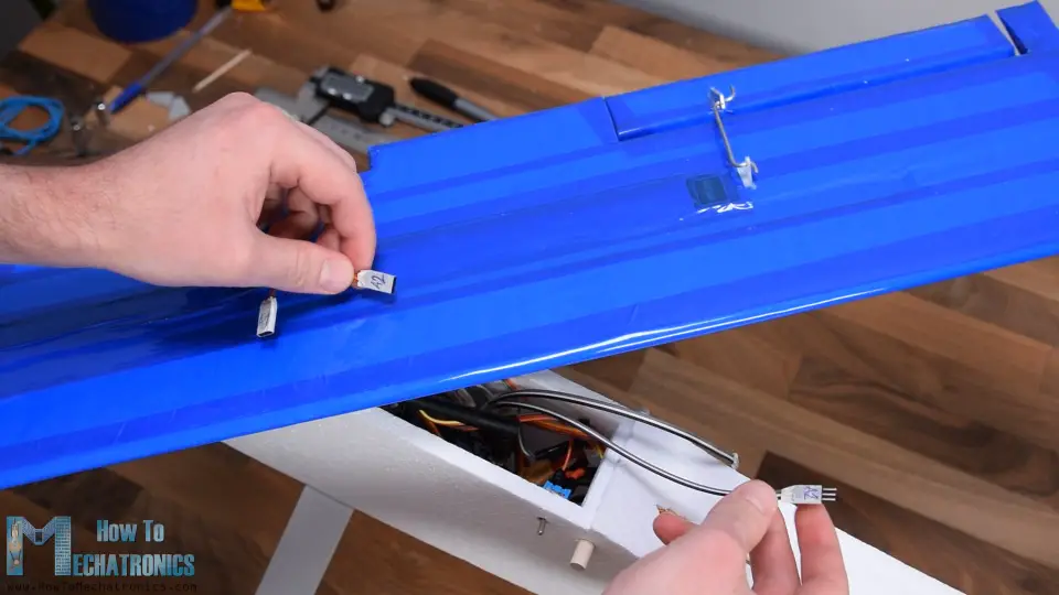
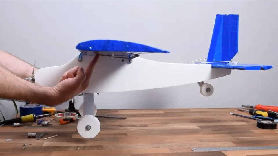
So, in one case I connected the battery to the ESC, I squeezed everything in. Finally, using the extension cables I tin can easily connect the wing ailerons to the receiver and then secure the wing to the fuselage.
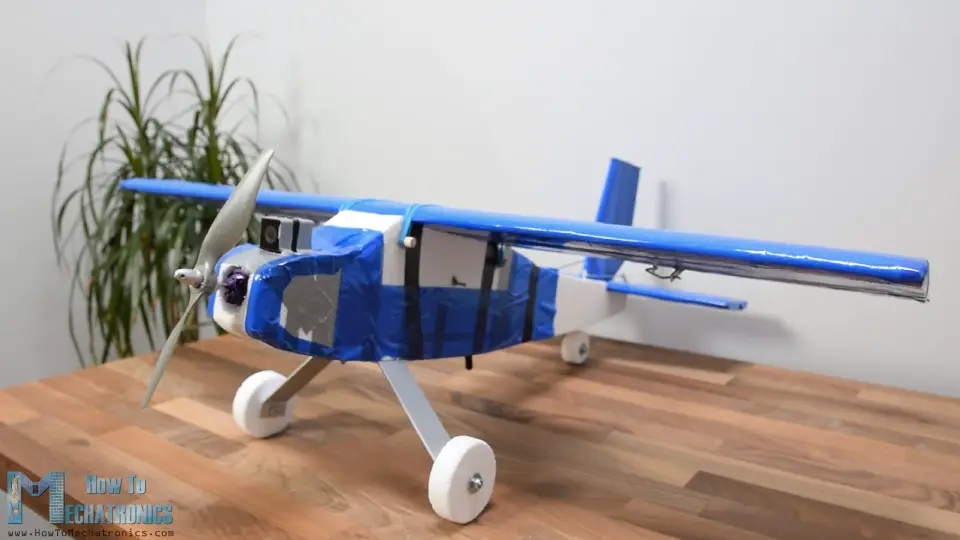
On the front, I fastened the propeller to the motor and what's left now is to check the CG or the centre of gravity of the aeroplane.
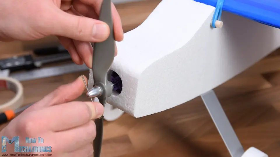
The CG is probably the most important factor whether the plane volition fly well or fly at all.
The airplane initially was tail heavy so I moved the battery to the forepart and added some weight (some bolts and nuts) and it got counterbalanced.
That'due south information technology, our Arduino based RC plane is now washed and we can go outside to try information technology out.
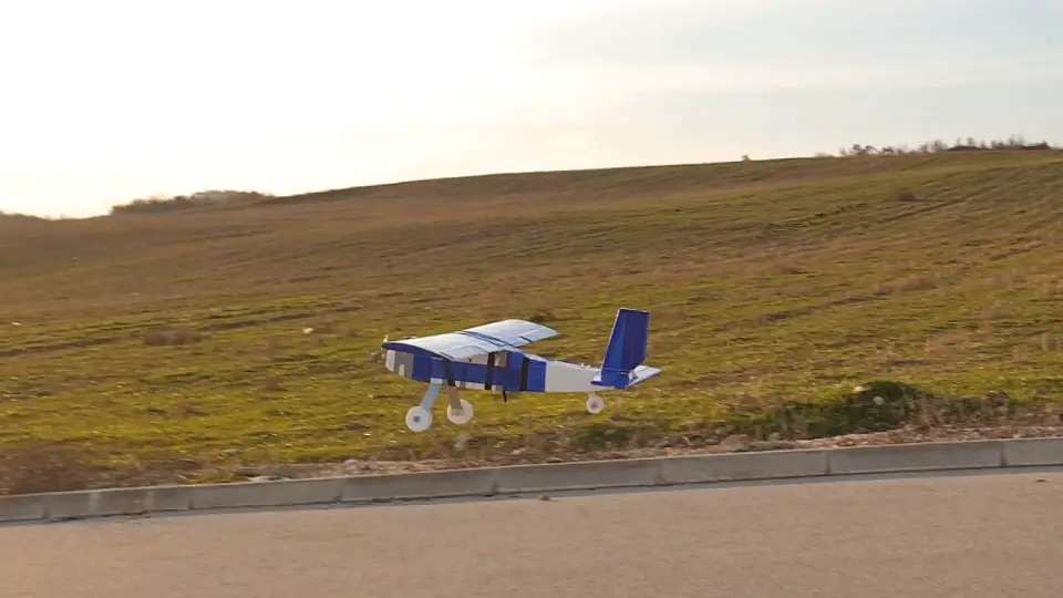
Testing the Arduino RC Airplane
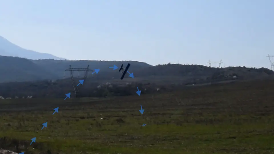
Well, the kickoff try or the maiden flight was not and then cool. Peculiarly after seeing the outcome of the vanquish.
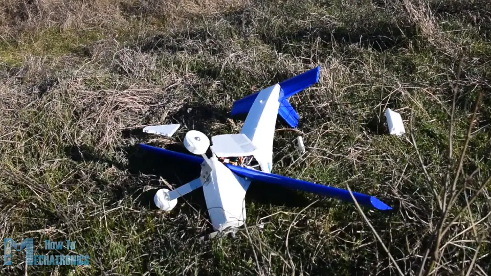
My conclusion here was that the airplane was all the same tail heavy and it felt like the motor didn't have enough power. Every bit I didn't have another motor or propeller to effort, I modified the nose of the aeroplane to be a bit smaller, moved the motor more than to the front then information technology has better airflow and besides rounded the edges on the front. Every bit for the structure I reinforced it with some wooden sticks and aluminum profiles that I glued in the inside surface area of the fuselage.
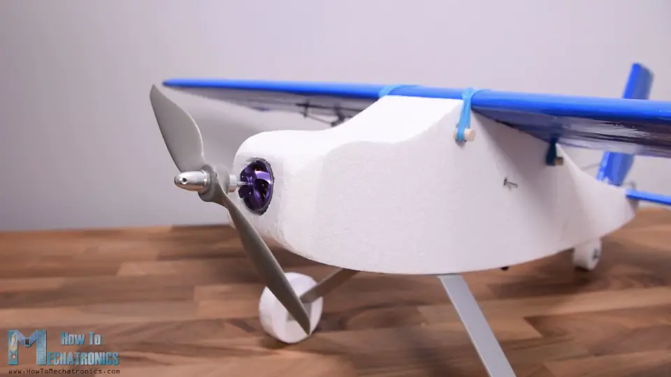
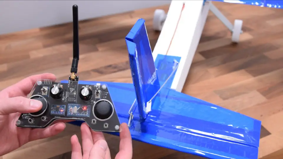
At the bottom of the electronics compartment I fabricated ii holes, one for the air to escape that comes from the front end opening, and the other for getting the NRF24L01 antenna outside for having batter range.
Ok so hither'due south attempt number two. Again, almost the aforementioned thing, though it felt like it had ameliorate airflow or ability at present.
The fuselage broke again, which tells that this Styrofoam is pretty weak for this purpose. I made a new fuselage, and this time used a picayune scrap of duct tape for reinforcing it.
Try number three. It looked promising but the terrain I accept for takeoff is actually not good at all. The plane started moving to the right, hit the edge of the road and broke once again.
I repaired it and this time wrapped almost the entire fuselage with duct and packing record. I should have done that much earlier as this gave the correct strength to the fuselage and it didn't break fifty-fifty after several more than crushes.
The problem now was that after several crushes I broke all 4 propellers that I had and so in this try I'grand using a glued propeller. Of course, the propeller teared apart at takeoff.
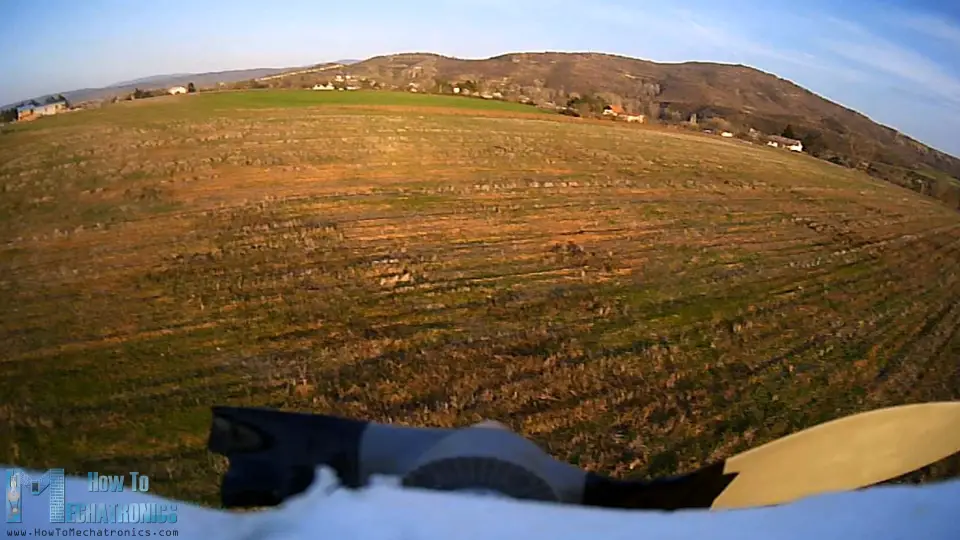
I tried with another glued propeller made out of two already cleaved propellers and this time I was actually lucky and the airplane finally took off properly.
Well the luck didn't last for long as the propeller bankrupt again in midair.
Still, as this was my first e'er experience with flying an RC airplane, I guess I can consider this projection successful, as I managed to prove the concept of making an entirely Arduino based system for controlling RC airplanes.
Other than that, we can note from the flight that the controls coming from the Transmitter are actually too harsh. That's because the joysticks are not good at all for this purpose, they have small motility range and bad response.
In gild to solve this, I added a feature to the program through which nosotros can command the responsiveness of the controls using the right potentiometer on the transmitter. Also, I added a function through which nosotros tin trim the rudder using the left potentiometer.
Arduino RC Plane Code
And then finally, let's take a expect at the Arduino code of this Arduino based RC aeroplane and wrap this project up. The code is exactly the aforementioned as explained in the previous tutorial, for controlling servos and brushless motors using the NRF24L01 transceiver modules.
Here's the complete code for this Arduino RC plane project:
/* Arduino RC Airplane == Receiver Lawmaking = past Dejan, www.HowToMechatronics.com Library: TMRh20/RF24, https://github.com/tmrh20/RF24/ */ #include <SPI.h> #include <nRF24L01.h> #include <RF24.h> #include <Servo.h> #define led nine RF24 radio (3, ii) ; // nRF24L01 (CE, CSN) const byte address[6] = "00001"; unsigned long lastReceiveTime = 0; unsigned long currentTime = 0; Servo throttle; // create servo object to control the ESC Servo rudderServo; Servo elevatorServo; Servo aileron1Servo; Servo aileron2Servo; int throttleValue, rudderValue, elevatorValue, aileron1Value, aileron2Value, travelAdjust; // Max size of this struct is 32 bytes - NRF24L01 buffer limit struct Data_Package { byte j1PotX; byte j1PotY; byte j1Button; byte j2PotX; byte j2PotY; byte j2Button; byte pot1; byte pot2; byte tSwitch1; byte tSwitch2; byte button1; byte button2; byte button3; byte button4; }; Data_Package data; //Create a variable with the to a higher place structure void setup () { Serial.begin(9600); radio.begin(); radio.openReadingPipe(0, address); radio.setAutoAck(false); radio.setDataRate(RF24_250KBPS); radio.setPALevel(RF24_PA_MAX); radio.startListening(); // Set the module as receiver resetData(); throttle.attach(10); rudderServo.adhere(4); // CH1 elevatorServo.adhere(five); // CH2 aileron1Servo.attach(half-dozen); // CH3 aileron2Servo.adhere(7); // CH4 pinMode(led, OUTPUT); // CH6 } void loop () { // Check whether nosotros keep receving data, or nosotros have a connexion between the two modules currentTime = millis(); if ( currentTime - lastReceiveTime > 1000 ) { // If current time is more then ane second since we have recived the last data, that means we take lost connection resetData(); // If connexion is lost, reset the data. Information technology prevents unwanted beliefs, for example if a drone jas a throttle up, if nosotros lose connection information technology tin can keep flying away if we dont reset the office } // Cheque whether in that location is data to be received if (radio.available()) { radio.read(&data, sizeof(Data_Package)); // Read the whole information and store it into the 'data' structure lastReceiveTime = millis(); // At this moment we have received the data } // Decision-making throttle - brushless motor with ESC throttleValue = constrain(data.j1PotY, 80, 255); // Joysticks stays in middle. So we but need values the upper values from 130 to 255 throttleValue = map(throttleValue, 80, 255, 1000, 2000); throttle.writeMicroseconds(throttleValue); // Adjusting the servos responsiveness travelAdjust = map(data.pot2, 0, 255, 0, 25); // Elevator control elevatorValue = map(data.j2PotY, 0, 255, (85 - travelAdjust), (35 + travelAdjust)); elevatorServo.write(elevatorValue); // Ailerons control aileron1Value = map(information.j2PotX, 0, 255, (x + travelAdjust), (80 - travelAdjust)); aileron1Servo.write(aileron1Value); aileron2Servo.write(aileron1Value); // Rudder trimming function if (information.j1PotX > 127) { rudderValue = information.pot1 + (data.j1PotX - 127); } if (information.j1PotX < 127) { rudderValue = information.pot1 - (127 - data.j1PotX); } // Rudder control rudderValue = map(rudderValue, 0, 255, (10 + travelAdjust), (90 - travelAdjust)); rudderServo.write(rudderValue); // Monitor the bombardment voltage int sensorValue = analogRead(A3); float voltage = sensorValue * (five.00 / 1023.00) * 3; // Catechumen the reading values from 5v to suitable 12V i // If voltage is below 11V turn on the LED if (voltage < eleven) { digitalWrite(led, Loftier); } else { digitalWrite(led, Depression); } } void resetData () { // Reset the values when there is no radio connection - Set initial default values data.j1PotX = 127; information.j1PotY = lxxx; // Motors stops // the key point of the joystick is not starting point for the throttle, its at value of 80 instead of 127 data.j2PotX = 127; data.j2PotY = 127; data.j1Button = ane; data.j2Button = 1; data.pot1 = 1; information.pot2 = 1; data.tSwitch1 = 1; data.tSwitch2 = 1; data.button1 = ane; information.button2 = 1; data.button3 = ane; information.button4 = one; }
Lawmaking language: Arduino ( arduino ) Description: I volition just quickly explicate the master functions of the lawmaking and for all other details you can bank check the previous tutorial. Then, after receiving the data coming from the transmitter, we utilise the Joystick1 Y axis value for decision-making the throttle of the aeroplane. We convert the values from fourscore to 255 coming from the transmitter into values from 1000 to 2000 which are used for controlling the brushless motor.
For controlling the elevator, we use the Joystick2 Y axis value which we convert to values from 85 to 35. These values direct set the position of the servo motor in degrees. Correct adjacent to them we can annotation that we have the travelAdjust variables, which value depends on the position of the right potentiometer. We actually utilise that value to decrease the position or the movement of the servos although the joysticks will go to their maximum position.
The same principle is applied for decision-making the ailerons and the rudder. Additionally, we utilise the data from the left potentiometer to adjust the neutral point of the rudder.
Lastly, using the analogRead() role and some math we command the battery voltage indicator LED.
Then that'south information technology. I would like to hear your thoughts nearly this projection in the comments section below, peculiarly from y'all who have experience with building and flying RC airplanes. For those who are beginners and thinking of getting into this, I would suggest to cheque the FliteTest YouTube channel because it's an astonishing resource for learning about this RC world. I volition put a link to it in the description.
I promise you enjoyed this project and learned something new. Feel free to ask any question in the comments section below and don't forget to cheque my Arduino Projects Collection.

Source: https://howtomechatronics.com/projects/arduino-rc-airplane-diy/
Posted by: anthonyeposis.blogspot.com
0 Response to "How To Draw Model Airplane Plans"
Post a Comment